3-Axis Registration Adjustment Simulator
Automatic and semi-automatic screen printing presses with a three-axis registration system — one lateral axis (X) and two independent front-back axes (Y1, Y2) — are unforgiving teachers: every practice attempt costs you substrate, ink, and time. This simulator lets you make those mistakes for free. It reproduces the four registration marks of a two-layer job, a hidden misalignment, and three virtual handwheels that behave like the real ones. Drag to rotate, tap for one-division nudges, and learn the adjustment sequence before you ever touch the machine.
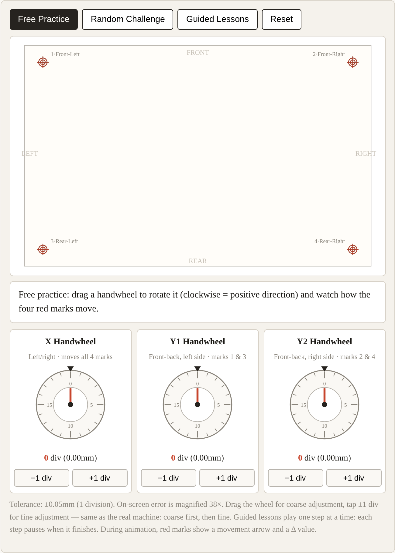
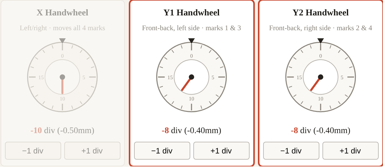
Tolerance: ±0.05mm (1 division). On-screen error is magnified 38×. Drag the wheel for coarse adjustment, tap ±1 div for fine adjustment — same as the real machine: coarse first, then fine. Guided lessons play one step at a time: each step pauses when it finishes. During animation, red marks show a movement arrow and a Δ value.
How to use it
Four modes, in the order I'd hand them to a new operator:
- Guided Lessons — five typical error patterns, animated step by step: pure X shift, pure Y shift, pure rotation, a mixed real-world case, and the one no handwheel can fix (stretch). Watch each one, ideally twice.
- Free Practice — no error loaded. Turn each handwheel and just watch which marks move and in what direction. Build the mental map: X moves all four marks sideways; Y1 moves the two left marks; Y2 moves the two right marks.
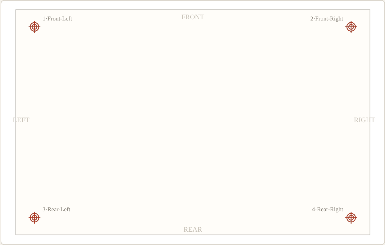
- Random Challenge — the simulator loads a hidden misalignment. Bring all four red marks onto the black ones within ±1 division, in as few turns as possible. If you're stuck, Show Me Step by Step walks you through the correct solution — which wheel, which direction, how many divisions, and why.
- Reset — zero everything.

The on-screen error is magnified 38× so you can see it; the handwheel readouts always show real millimetres. One division is assumed to be 0.05 mm with 20 divisions per turn — check this against your own machine's scale before applying the habits.
The one concept that makes three axes simple: the common component
Operators who struggle with Y1/Y2 usually struggle because they see two front-back adjustments. Experienced operators see one shared movement plus one difference. This is the single most useful idea in three-axis registration, so here it is properly.
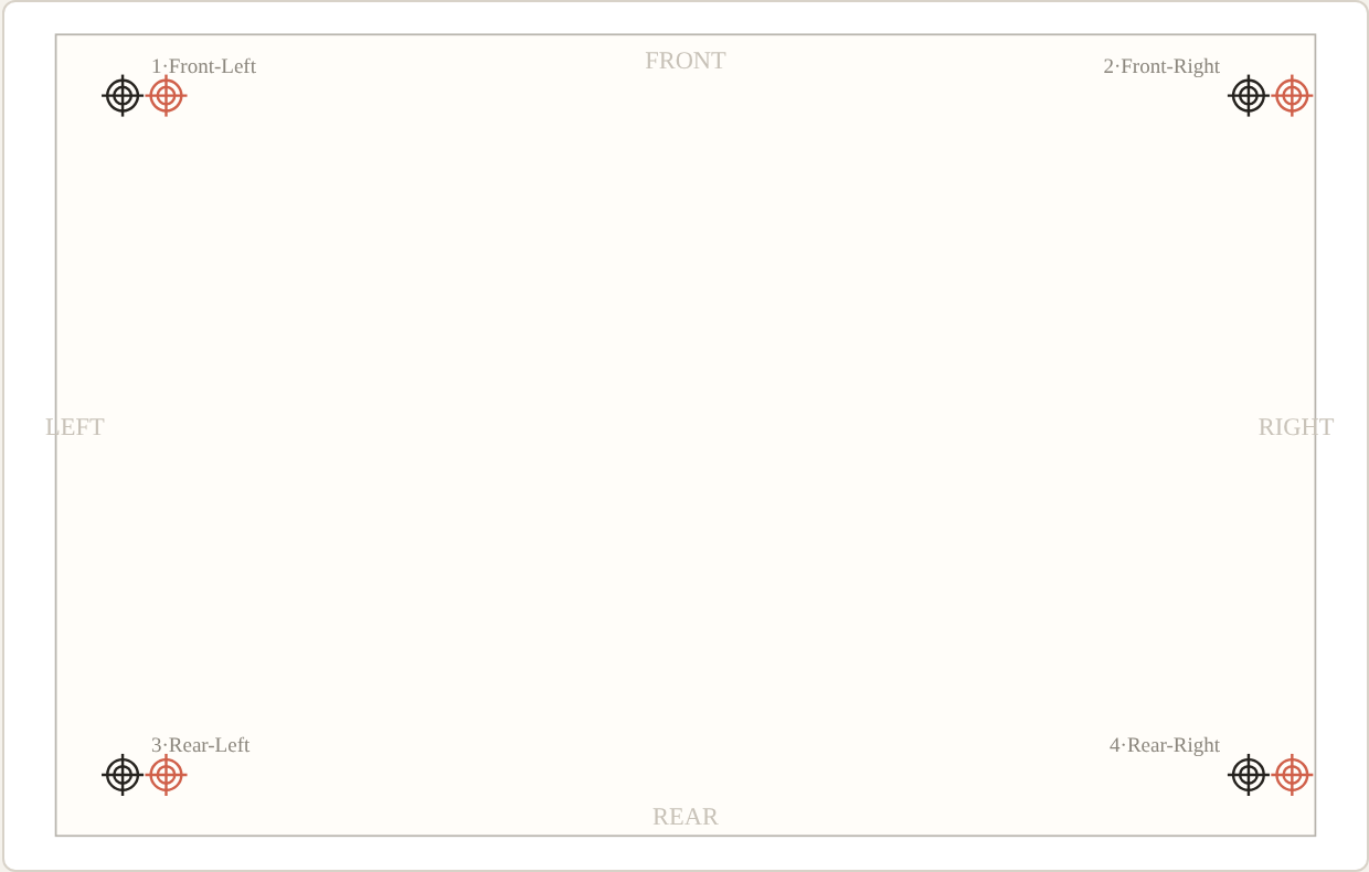
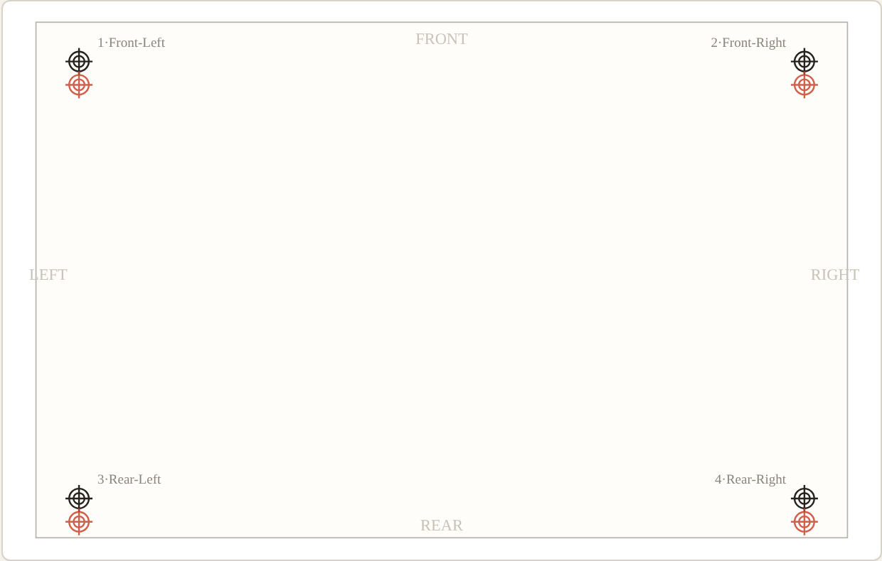
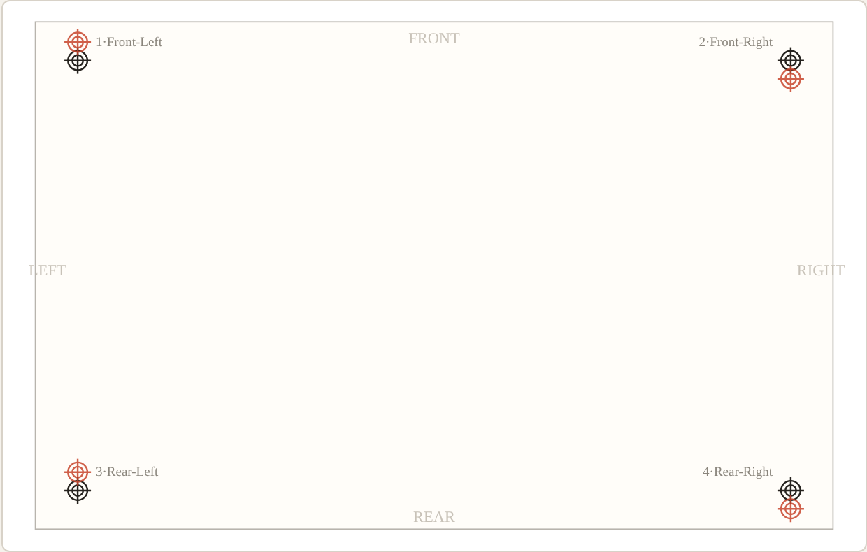
Take whatever front-back error you measure on the left side and on the right side, and split it into two parts:
- The common component — the part both sides share:
(left + right) ÷ 2. Both Y1 and Y2 turn in the same direction, by the same amount to remove it. The whole screen shifts forward or backward as one rigid piece. No rotation is introduced. - The differential component — what's left after the common part is removed:
(right − left) ÷ 2on each side, in opposite directions. Y1 and Y2 turn in opposite directions, by the same amount. The screen pivots around its centre. Pure rotation, no net shift.
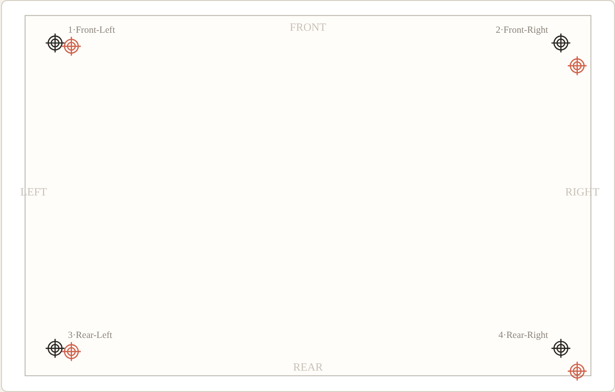
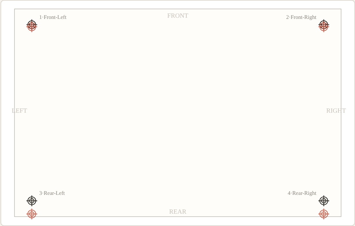
Any front-back error is exactly these two parts added together. A worked example from Lesson 4: after X is fixed, the left marks are off by 0.10 mm toward the rear and the right marks by 0.70 mm. Split it:
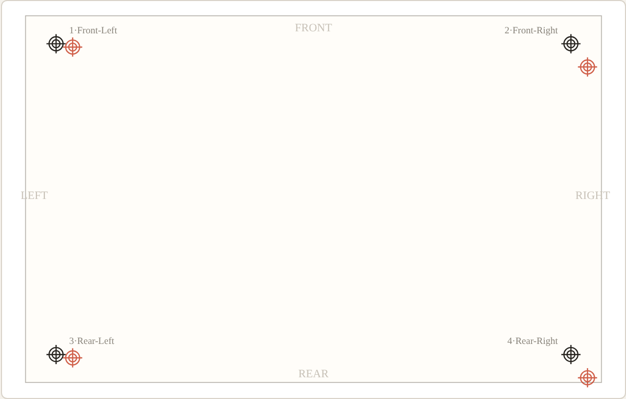
- Common component: (0.10 + 0.70) ÷ 2 = 0.40 mm → turn Y1 and Y2 together, 8 divisions each (at 0.05 mm/div), toward the front.
- What remains: left 0.10 − 0.40 = −0.30, right 0.70 − 0.40 = +0.30 — equal and opposite, i.e. pure rotation → turn Y1 and Y2 in opposite directions, 6 divisions each.
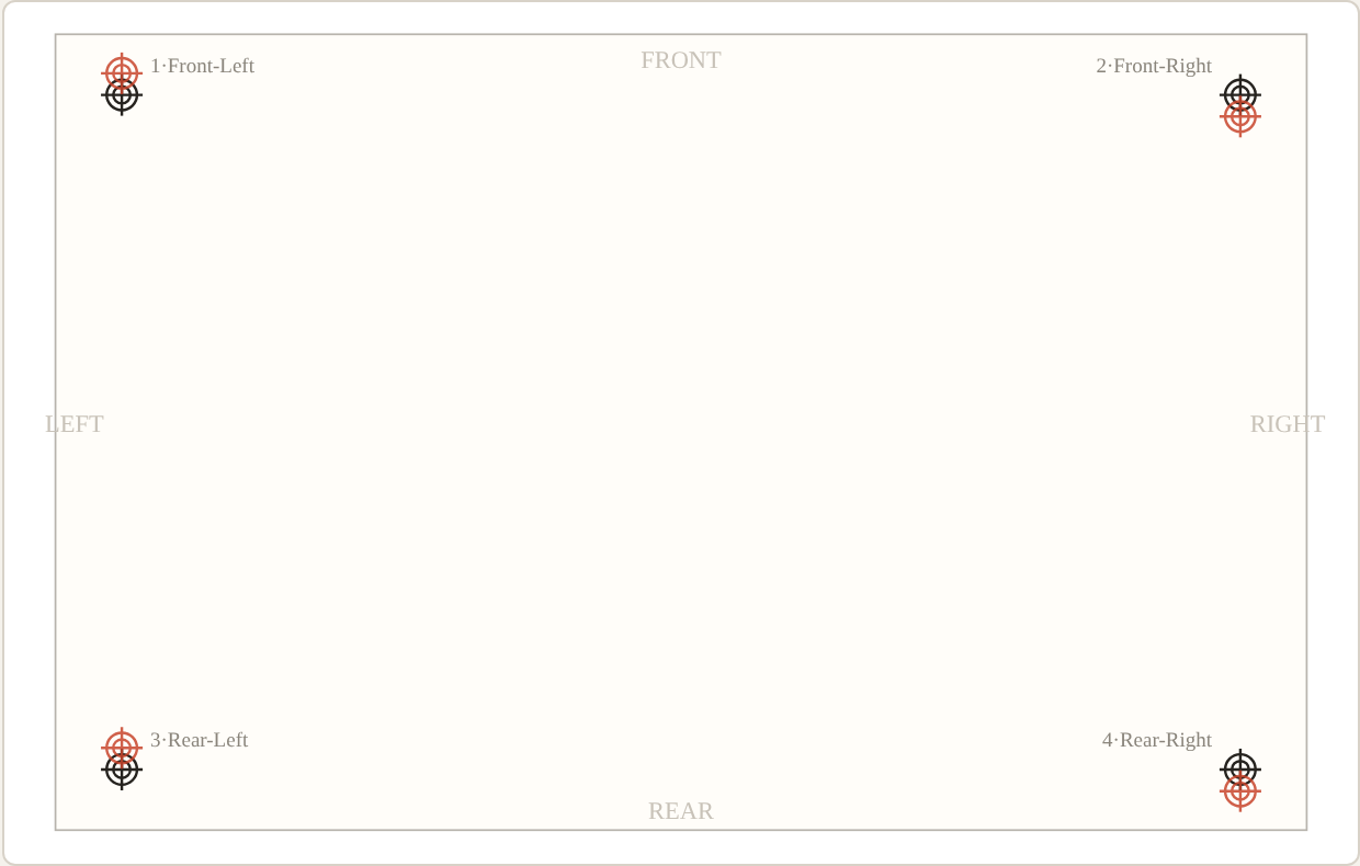
0.40 + 0.30 = 0.70 on the right, 0.40 − 0.30 = 0.10 on the left — the split adds back up exactly. Once you can do this decomposition in your head, Y1 and Y2 stop being mysterious: same-direction turns shift, opposite-direction turns rotate, and every real error is some mixture of the two.
The sequence that saves turns
Fix X first, then the common Y component, then rotation last. Rotation is last for a physical reason: the screen pivots around its centre, so any rotation correction moves every mark's position slightly — if you rotate first, your earlier translation readings were taken on a crooked screen and you'll re-do them. In this simulator the axes are perfectly independent, as they are on servo-driven presses; on the real machine, print one test sheet between major steps and re-measure all four marks before deciding the next move.
What the handwheels cannot fix
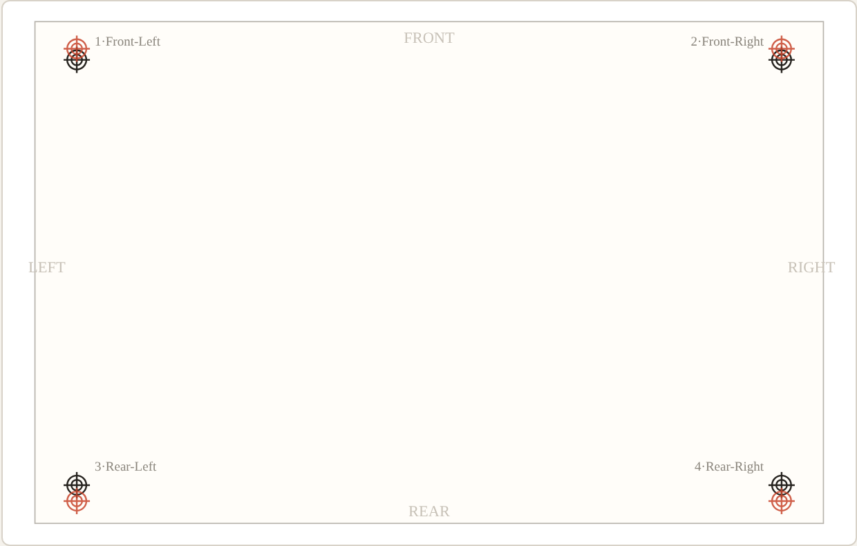
Lesson 5 shows the pattern that fools everyone once: the rear marks are off more than the front marks, and no combination of X, Y1 and Y2 gets all four aligned. That's not misregistration — the mesh has been stretched along the print direction by the squeegee, and the printed image is physically longer than the first layer. Positioning axes move the screen; they cannot un-stretch an image. The fixes live elsewhere: screen warping / stretch compensation if your press has it (set separately for left and right), and checking squeegee pressure, snap-off distance, and screen tension. Learning to recognise this pattern early — instead of burning an hour chasing it with handwheels — is worth the whole simulator.
Scope and honest limits
This is a training aid, not a digital twin of your press. Axis direction conventions, divisions per millimetre, and which side Y1 controls vary by manufacturer — verify them on your machine (the assumptions here: X positive rightward, Y positive toward the rear, Y1 left side, 0.05 mm per division). Real machines add effects the simulator deliberately omits in its default mode: mesh relaxation after adjustment, clamp settling, and backlash. The patterns it teaches — read before you touch, split common from differential, translate before you rotate, recognise stretch — transfer to any three-axis system.
Related: the Registration Mark Generator for putting the marks on your films in the first place, and the Screen Mesh Selector for the screen itself.